3.1 Forces acting on the floating magnetic liquid bead
When a liquid bead when is placed on the surface of a water-filled container, it remains buoyant at the water-air interface, as depicted in Fig. 2. This buoyancy results from the equilibrium between downward gravitational force, upward forces of buoyancy acting on the bead and surface tension of the water. Zhang et al. (2012) have extensively examined and discussed the characteristics of the vertical magnetic forces. In the current investigation, our focus is on forces acting in horizontal direction. Two horizontal forces act on the bead floating on water surface, and the equilibrium of these forces is mathematically described by Eq. 1
$${m}_{p}{a}_{p}{=F}_{m}+{F}_{d}$$
1
Where, \({m}_{p}\) and \({a}_{p}\) are mass and acceleration of the bead. \({F}_{m}\) is magnetic force and \({F}_{d}\) is drag force acting on the bead.
Assuming the surrounding medium to be diamagnetic, the driving force acting on a floating bead is described as per previous studies (Nguyen et al. 2010; Shevkoplyas et al. 2007).
$${F}_{m}=\frac{V\chi }{{\mu }_{o}}B\frac{dB}{dx}$$
2
Here, \({F}_{m}\) represents the magnetic force, \(V\)denotes the volume of the magnetite, \(\chi\) is the magnetic susceptibility of the floating bead, \({\mu }_{o}\) is the permeability of vacuum, and \(B\) represents the magnetic flux density.
Drag force emerges when an object moves at a relative velocity with respect to its surrounding fluid. This force originates from the necessity to displace the fluid elements in the path of the moving object. The drag force acting on a partially submerged spherical particle is described by Stokes' law:
$${F}_{d}=6\pi \beta \mu {r}_{p}{\upsilon }_{p}$$
3
Where \(\beta\) is correction factor for coefficient of friction, \(\mu\) is the dynamic viscosity of fluid, \({r}_{p}\) and \({\upsilon }_{p}\) represents the radius and horizontal velocity of the bead respectively. As reported in our previous work, \(\beta\) is dependent on the degree of perturbation in the liquid interface (Ooi et al. 2016). This perturbation, in turn, depends on both the meniscus angle (ψ) and the submerged depth of the liquid bead, Fig. 2. The bead was assumed to be a solid spherical body which maintains its shape during the motion.
As per Eq. 2, we learnt the magnetic force varies proportionally with volume of the magnetite, flux density and flux density gradient of the magnetic field and the concentration of the magnetite particles (Khaw et al. 2016). This relationship is corroborated by Fig. 4(a), where liquid beads with 2% (wt) magnetite particles experience more force compared with 1% (wt) liquid bead. Assuming a uniform distribution of magnetite particles throughout the TMPTMA, the overall volume remains constant for all core-shell beads. In the case of a solid bead without a core, the volume available to magnetite particles increases by 15%. Additionally, the solid bead is 5% lighter than the core-shell. Thus, the solid beads experience more force compared to core-shell for same magnetite concentration, Fig. 4(b).
The magnetic flux density (B) of the magnet was measured using a handheld commercial gaussmeter (GM07, measurement range: 0 to 3 T, Hirst Magnetic Instruments Ltd, UK). The magnet is vertically affixed to a PMMA holder, positioned on the linear stage. Initially, the probe makes contact with the magnet to obtain the maximum reading. Subsequently, the linear stage is programmed to incrementally move 0.5 mm away from the probe for each measurement. Figure 5(a) illustrates the magnetic flux densities recorded as the distance between the gaussmeter probe and the magnet increases.
As demonstrated in Fig. 5(b) the floating magnetic bead starts experiencing magnetic force at 3mm. This helped us in designing the sorting microfluidic device where beads flowing through the channels remained within the range of magnetic influence. The displacement and distance of influence for beads carrying of 2%(wt) magnetite particle is more than their 1%(wt) counterpart. This observation holds true for solid beads when compared with core-shell beads.
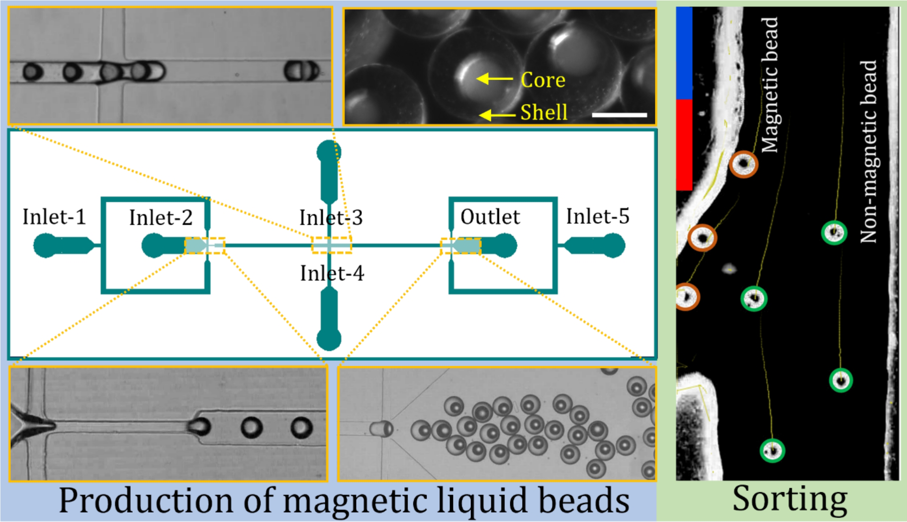
3.2 Sorting
The magnetic and non-magnetic beads were collected after curing and then redispersed in water for sorting. Hydrophobic nature of the beads enabled us to utilise a PVA deposition strategy to facilitate their collection into a glass syringe through PTFE tubing. A 10% PVA solution was flushed into the syringe and tubing for 10 minutes, followed by a 15-minute baking process at 100°C. This process was repeated three times to achieve a desired level of hydrophilicity and prevented adhering of the beads to the syringe and tubing walls.
In this work, we showcase the sorting of magnetic and non-magnetic beads based on magnetic forces. We introduced two flow streams into a central channel: one containing a mix of magnetic and non-magnetic beads dispersed into water, and the other containing a buffer. The streams are separated into two outlet streams downstream, Fig. 3. The optimised flow rates for the buffer and the beads dispersed medium were set at 8 ml/hr and 4 ml/hr, respectively. The trajectories of 100 µm-sized magnetic and non-magnetic beads were observed within the microfluidic device. The deflection of beads depends on the balance between the magnetic force and the hydrodynamic drag force. Outlet 1 (0.5×1mm) branches out at a 30° angle from the straight outlet 2 (1×1mm). This design ensures that magnetic beads, under influence of the magnetic force deviate from straight path and exit from outlet 1, while non-magnetic beads continue along the straight path and exit from outlet 2, Video 1.
To evaluate sorting efficiency, bead motion was monitored using the ImageJ plugin TrackMate. The trajectories of beads over the last 10 frames are illustrated by the tails in Fig. 6(a). All the Beads depicted in Fig. 6(a[1]) maintain straight trajectories and emerge solely from outlet 2 in the absence of the magnet. In Fig. 6(a[2]), beads exhibit deviation from a straight path, adhere to the channel wall, and travel along the wall under magnetic influence. The beads exiting from outlet 1 are classified as magnetic, while those exiting from outlet 2 are categorised as non-magnetic. Additionally, about 10% beads exit from outlet 1 without adhering to the channel wall, leading to sorting error. Conversely, none of the beads after adhering to the channel wall exited from outlet 2. Figure 6(b) presents the outcomes, indicating that 90% of beads collected at outlet 1 were magnetic, while all beads collected at outlet 2 were non-magnetic.